Tendons Curving Around Openings? Watch Plan Curvature
When PT tendons sweep around a slab opening, the plan curve adds friction and pushes on the concrete with about P/R per metre. Keep radii generous and add hairpins.

The tendon profile turns prestress into load balancing, and the layout decides how buildable the slab is. Banded and distributed tendons, drape and reverse curves, minimum radius, cover and spacing, with the rules from ACI 318, PTI, Eurocode 2 and TR43.
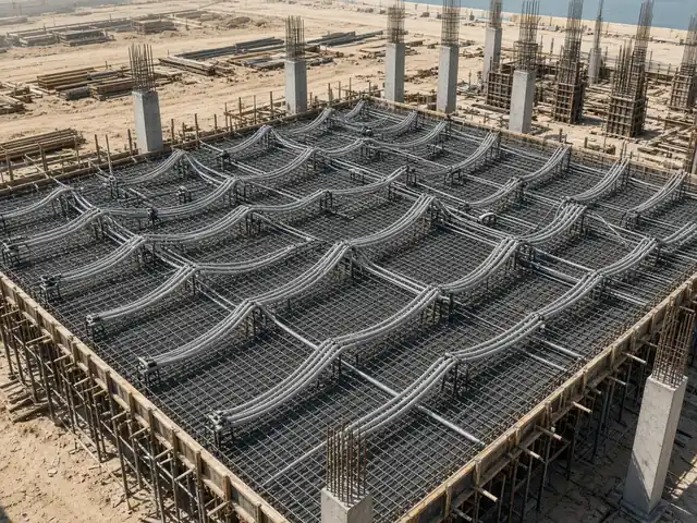
When PT tendons sweep around a slab opening, the plan curve adds friction and pushes on the concrete with about P/R per metre. Keep radii generous and add hairpins.
How banded and distributed tendon layouts differ, and the code rules that govern the mix in a PT floor.
A post-tensioned slab works because the tendons are curved. The curvature creates the upward balancing load (see precompression and balanced load), so the profile is as important as the force. The layout in plan, meanwhile, decides how the tendons pass between columns, around openings and over each other, which is what the site crew actually has to build. This guide covers both.
In a continuous span the tendon is high over the supports and low near midspan. A single parabola from support to support would have a sharp kink over the column, so the profile is made of three parabolic segments: a long sagging parabola in the span and short hogging (reverse) parabolas over each support, meeting at inflection points. The inflection point is often placed at about 5 to 10 percent of the span from the support centreline.
For a span with the high points at heights y1 and y2 and the low point at ylow, the drape used in load balancing is the distance from the low point to the line joining the inflection points, which is slightly less than the full geometric drop. The reverse curves produce concentrated downward loads near the supports, roughly equal to the upward load lost by the shorter span parabola; most design programs, including RAM Concept, calculate these equivalent loads directly from the profile.
Sagging parabola: wup = 8 P as / Ls² Reverse parabola: wdown = 8 P ar / Lr²
End spans need care: the tendon usually ends at mid-depth (or slightly above) at the slab edge to keep the anchorage centred, which reduces drape in the end span. Designers compensate with extra tendons in end spans, a shorter end span, or added reinforcement.
The most common layout for flat slabs is banded in one direction and distributed in the other. Bands of tendons run along the column lines, and uniformly spaced tendons run across them. Because the tendons in the two directions are draped, one set must be placed over the other at every crossing; the banded-distributed arrangement makes that easy, since the distributed tendons simply drape over the bands.
Research and the ACI 318 commentary support the banded-distributed approach for two-way slabs, provided the minimum precompression and the spacing limits are met.
ACI 318-19 §8.7.5.4 limits the spacing of tendons or groups of tendons in at least one direction to the lesser of 8h and 1.5 m in two-way slabs with uniformly distributed loads, and requires extra attention where concentrated loads or openings occur. TR43 gives similar guidance for UK practice. Minimum clear spacing between ducts or tendon bundles is set by concrete placement and the anchorage dimensions; anchorages need enough edge distance and spacing to fit the bursting reinforcement (see anchorage zone design).
Indicative values. The 8h / 1.5 m spacing limit is quoted from ACI 318-19 as we understand it. Check the clause number and wording in the edition adopted for your project.
Tendons cannot bend sharply. Each PT system specifies a minimum radius of curvature for its strand and duct; for monostrand tendons in slabs this is typically a few metres in the vertical plane. Tight curves increase friction losses and radial forces on the concrete (see friction and wobble losses). Horizontal curves around openings and columns also produce lateral forces that need hairpin or U-bar reinforcement where the tendon is close to an edge. EN 1992-1-1 §8.10.4 and the PT system's European Technical Assessment set the requirements for anchorage and deviators.
Radial force per unit length: pr = P / R
For example, a 150 kN monostrand around a 3 m horizontal radius pushes outwards with about 50 kN/m, which matters if the tendon passes close to a slab edge or an opening.
Cover to tendons is set by durability, fire and the PT system:
Tendon heights are shown as support (chair) heights at regular spacing on the shop drawings, measured from the soffit to the underside of the tendon. Typical support spacing is around 1 m; check the system and project specification. The tendon must also clear the top and bottom reinforcement mats.
Slab 220 mm, 12.7 mm monostrand (sheathing diameter about 15 mm), top cover to tendon 25 mm, bottom cover 25 mm, top bars 12 mm in the other direction above the tendon at the column:
Centroid of tendon at high point ≈ 220 − 25 − 12 − 7.5 = 175.5 mm from soffit
Centroid at low point ≈ 25 + 7.5 = 32.5 mm from soffit
Geometric drop ≈ 143 mm; effective drape after reverse curves ≈ 130–140 mm
These numbers feed directly into the balanced load. Every 10 mm of lost drape reduces the balancing load by about 7 percent in this slab.
Indicative values. Cover, bar sizes and sheathing dimensions are illustrative. Use the project durability and fire requirements and the PT system data.
Tendons are swept around openings with gentle horizontal curves, keeping the minimum radius and a clear distance to the opening. Large openings may need tendons to be terminated with intermediate anchorages. See openings and penetrations in PT slabs for the planning rules.
| Item | Typical rule | Reference |
|---|---|---|
| Profile | Reversed parabolas; inflection about 0.05–0.1L from support (indicative) | Design practice; PTI, TR43 |
| Balancing load | 8Pa/L² per parabolic segment | Mechanics |
| Layout | Banded on column lines one way, distributed the other | ACI 318-19 commentary; TR43 |
| Maximum spacing (two-way slab) | Lesser of 8h and 1.5 m (indicative) | ACI 318-19 §8.7.5.4 |
| Minimum radius | From the PT system data | System ETA / approval |
| Radial force | P/R per metre | Mechanics |
| Cover | Durability, fire and system requirements | ACI 318-19 §20.5; EN 1992-1-1 §4.4; EN 1992-1-2 |
We prepare tendon layouts and profiles as part of our post-tension design package and check them in PT shop drawings.
Part of our PT design guides. Codes are referred to by clause where we are confident of the reference, and coefficients marked indicative should be checked against the code text; always check the edition and national annex adopted for your project. Worked examples are illustrative, not designs.
A series of reversed parabolas: high over the supports, low near midspan, with short reverse curves near each support meeting the span parabola at inflection points.
Banding along the column lines with distributed tendons the other way avoids weaving, concentrates balancing load at the columns and provides vertical prestress for punching shear.
ACI 318-19 limits the spacing of tendons or tendon groups in at least one direction to the lesser of 8h and 1.5 m in two-way slabs with uniform loads. Check your adopted edition.
From the slab thickness, the covers, the reinforcement layers that the tendon passes and the tendon diameter. The effective drape is measured between the low point and the line joining the inflection points.
It is set by the PT system documents for the strand and duct type. Tight radii increase friction and radial forces.
The design drawings set the profile, and the shop drawings translate it into support heights at regular spacing. We check both.
Technical information only. This article is general engineering information to help you understand the subject. It is not design advice for a specific project, codes and authority requirements change, and worked examples are illustrative. Designs must be prepared and checked by a qualified structural engineer responsible for the project, to the code edition adopted for the project. Disclaimer · Terms of use.
WhatsApp or email the architectural or structural set, the location and what you need. The reply comes from the engineers who will do the work, with a proposed scope and programme.