Tendons Curving Around Openings? Watch Plan Curvature
When PT tendons sweep around a slab opening, the plan curve adds friction and pushes on the concrete with about P/R per metre. Keep radii generous and add hairpins.

The force the jack applies is not the force along the tendon. How curvature friction, wobble and wedge draw-in reduce it, which coefficients to use under Eurocode 2 and ACI/PTI practice, and a worked example.
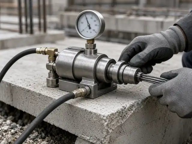
When PT tendons sweep around a slab opening, the plan curve adds friction and pushes on the concrete with about P/R per metre. Keep radii generous and add hairpins.
When a tendon is stressed, the jack pulls the strand through its duct or sheath. Friction between strand and duct resists that movement, so the force falls with distance from the jack. When the jack releases, the wedges seat and the strand pulls back slightly, which takes away more force close to the anchorage. Getting these short-term losses right matters twice: the effective force along the tendon is what the design relies on, and the same friction profile produces the calculated elongation that site teams check during stressing. For the wider picture of all losses, see our prestress losses overview.
Try your own tendon in our free PT tendon elongation calculator: friction and wobble along a segmented profile, one-end or two-end stressing, draw-in, the reading expected from the initial-load mark and the ±7% check, with PDF and CSV.
In ACI and PTI practice, the force at distance x from the stressing end is usually written as:
P(x) = P0 · e−(μθ + Kx)
where P0 is the jacking force at the anchorage, μ the curvature friction coefficient, θ the sum of the absolute angle changes in radians from the jack to point x, and K the wobble coefficient per unit length (per m or per ft).
EN 1992-1-1 clause 5.10.5.2 writes the loss in a slightly different form:
ΔPμ(x) = Pmax (1 − e−μ(θ + kx)) (5.45)
Here k is an unintentional angular displacement per unit length (radians per metre) and is multiplied by μ. The two forms describe the same physics, but the coefficients are not interchangeable: the Eurocode product μk corresponds to the ACI/PTI wobble coefficient K. Mixing the two, for example using a Eurocode k value as if it were K, is one of the most common errors we see in loss calculations.
Two practical points on θ:
The coefficients belong to the PT system, the duct type and the strand, so the values in the PT specialist contractor's approved system documents govern. The figures below are indicative ranges for preliminary design and checking only.
| Tendon type | μ | Wobble | Source |
|---|---|---|---|
| Internal bonded strand in a duct, Eurocode form | 0.19 | k = 0.005 to 0.01 rad/m | EN 1992-1-1, 5.10.5.2 and Table 5.1 (tendons filling about half the duct) |
| Unbonded greased and sheathed monostrand | 0.05 to 0.15 | K ≈ 0.0003 to 0.002 per ft (≈ 0.001 to 0.0066 per m) | Ranges commonly quoted from the PTI Post-Tensioning Manual and earlier ACI 318 commentary tables |
| Bonded strand in flexible metal duct | 0.15 to 0.25 | K ≈ 0.0005 to 0.002 per ft (≈ 0.0016 to 0.0066 per m) | As above |
For Eurocode-based projects, the European Technical Assessment (ETA) of the post-tensioning kit gives the friction and wobble values recommended for that system and duct. Plastic ducts, steel strip ducts and monostrands all have different values. When the system is not known at design stage, state the assumed coefficients on the drawings and in the calculation report, and recheck the losses and elongations once the approved system is confirmed.
As the jack releases, the strand pulls the wedges into the anchorage until they grip. This movement, the draw-in or wedge set, is typically a few millimetres; around 6 mm (1/4 in) is a common design value, but the approved system and the jack (with or without power seating) set the figure. The strand slips back over a length near the anchorage, and friction acts in reverse over that length.
If the friction loss per unit length p near the anchorage is taken as roughly constant, the affected length and the force loss at the anchorage are:
xset = √( Δset · Ep · Ap / p ) ΔPanchor ≈ 2 · p · xset
The force after lock-off is lowest at the anchorage and rises to meet the friction curve at xset. Beyond that point, draw-in has no effect. On short tendons, xset can exceed the tendon length and the whole tendon loses force, so draw-in becomes the dominant short-term loss. More precise calculations integrate the actual friction profile and iterate on xset.
This example uses assumed values to show the method. It is not taken from any project or PT system.
| x (m) | θ (rad) | μθ + Kx | P(x) (kN) |
|---|---|---|---|
| 0 | 0.000 | 0.0000 | 208.3 |
| 10 | 0.272 | 0.0493 | 198.3 |
| 20 | 0.544 | 0.0986 | 188.8 |
| 30 | 0.816 | 0.1480 | 179.7 |
The force at the dead end is about 180 kN, roughly 14% below the jacking force. In this example wobble contributes more than curvature, which is typical of long, gently draped slab tendons.
Draw-in. Over the first 20 m the friction loss averages p = (208.3 − 188.8) / 20 ≈ 0.98 kN/m. With a 6 mm draw-in:
xset = √(6 × 195,000 × 140 / 0.978) ≈ 12,939 mm ≈ 12.9 m
ΔPanchor ≈ 2 × 0.98 × 12.9 ≈ 25 kN
So the force just behind the anchorage after lock-off is about 183 kN, the highest force after lock-off is about 195 kN at around 13 m from the stressing end, and beyond that the friction curve is unchanged.
Illustrative example only: values assumed for explanation, not from any project or PT system.
The same profile gives the calculated elongation; we continue this example in our guide to tendon elongation calculation.
Stressing from both ends roughly halves the length over which friction accumulates, at the cost of a second stressing operation and access at both ends. It is usually considered for long tendons, tendons with many spans or large cumulative angle changes, and tendons where the dead-end force would otherwise fall too low for the design. The break-even length depends on the profile and the system, so the designer sets the stressing ends on the drawings. Short tendons are a different problem: there, draw-in rather than friction dominates.
Talk to us about friction losses and stressing data. Our team calculates friction, wobble and draw-in losses from the shop-drawing profiles for the approved system, and checks them in every PT design review. Ask about PT shop drawings, stressing supervision and elongation records or a full post-tension design package, read about our post-tension design in the UAE, or contact our engineers.
Related PT design guides: tendon profile and layout, precompression and balanced load.
Part of our PT technical series. Codes are referred to by clause where we are confident of the reference; always check the edition and national annex adopted for your project.
Curvature friction comes from the intended curvature of the tendon and depends on the friction coefficient μ and the angle change. Wobble comes from small unintended deviations of the duct along its length and is proportional to tendon length.
EN 1992-1-1 Table 5.1 gives μ = 0.19 for internal strand tendons that fill about half the duct, and clause 5.10.5.2 gives unintentional angular displacement k generally in the range 0.005 to 0.01 per metre. The ETA of the approved PT system governs.
No. In Eurocode 2, k is an angle per unit length and is multiplied by μ. In ACI and PTI practice, K is applied directly to the length. The Eurocode product μk corresponds to K.
A few millimetres. Around 6 mm (1/4 in) is a common design value for strand anchorages, but the approved system and the jack and seating method set the actual figure.
When the tendon is long, has many spans or a large total angle change, or when the force at the far end would otherwise be too low for the design. The designer shows the stressing ends on the drawings.
Yes. We calculate losses and elongations from the shop-drawing profiles using the approved system values, and review stressing records against them.
Most projects touch more than one of these. See all our PT design resources, or the Iron Axis home page for the full overview.
Elongation with friction, wobble and draw-in, expected site reading and the ±7% check (ACI and EC2).
Open the calculator →Creep, shrinkage, relaxation, elastic shortening, friction and draw-in to ACI or Eurocode 2, for 12.7 and 15.2 mm strand. Print, PDF and CSV.
Open the calculator →Elongations, sequence and record review.
Read more →The worked example continued.
Read more →Profiles, anchorages and stressing schedules.
Read more →All losses in one place.
Read more →Technical information only. This article is general engineering information to help you understand the subject. It is not design advice for a specific project, codes and authority requirements change, and worked examples are illustrative. Designs must be prepared and checked by a qualified structural engineer responsible for the project, to the code edition adopted for the project. Disclaimer · Terms of use.
WhatsApp or email the architectural or structural set, the location and what you need. The reply comes from the engineers who will do the work, with a proposed scope and programme.