PT Elongation Doesn't Match the Calc? Check These 4
Measured elongation off from the calculated value? Check friction and wobble, the strand modulus, seating loss and initial slack before you call it a tendon problem.

Elongation is the field check on prestress. How the calculated value is worked out, what corrections apply to what is measured on site, the usual tolerance, and what to do when a tendon does not match.
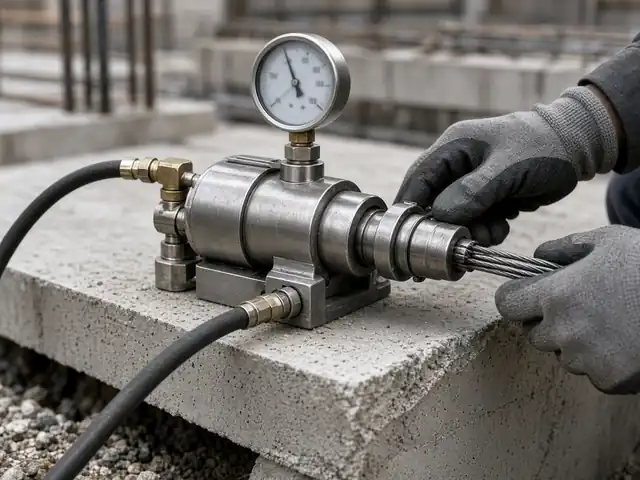
Measured elongation off from the calculated value? Check friction and wobble, the strand modulus, seating loss and initial slack before you call it a tendon problem.
Once a tendon is locked off, its force cannot be seen. The jack gauge shows the force at the anchorage at the moment of stressing, but not how much of it travelled along the tendon. Elongation does: it reflects the average strain over the stressed length. That is why every stressing record compares a measured elongation with a calculated one, and why the calculated value has to be right before stressing starts. This guide covers the calculation and the site checks; our elongation tolerances and records note covers what a good record contains.
Try your own tendon in our free PT tendon elongation calculator: friction and wobble along a segmented profile, one-end or two-end stressing, draw-in, the reading expected from the initial-load mark and the ±7% check, with PDF and CSV.
The extension of the strand is the integral of strain along its length:
Δ = ∫ P(x) dx / (Ap · Ep) ≈ Pavg · L / (Ap · Ep)
where P(x) is the force along the tendon after friction and wobble, L the stressed length, Ap the strand area and Ep the strand modulus. When the force follows the exponential friction curve P(x) = P0e−(μθ + Kx) over the full length, with a = μθ + KL at the far end, the average force is:
Pavg = P0 (1 − e−a) / a
For tendons with several curved segments, the calculation is normally done segment by segment and summed. Our guide to friction and wobble losses explains where μ, K and θ come from.
The calculated value must match the way elongation is measured on site. The method should be written down before stressing, because the corrections depend on it.
This continues the illustrative example in our friction and wobble guide. The values are assumed for explanation and are not taken from any project or PT system.
Pavg = 208.3 × (1 − e−0.1480) / 0.1480 ≈ 193.6 kN
Δ = 193.6 × 103 × 30,000 / (140 × 195,000) ≈ 213 mm
If elongation were measured from the jack ram with, say, 600 mm of free strand inside the jack, the extra extension of that length at the jacking force would be 208.3 × 103 × 600 / (140 × 195,000) ≈ 4.6 mm, giving about 217 mm at full pressure before lock-off. With a 20% initial load, the reading from the mark would be about 80% of that, around 174 mm, before extrapolation.
A ±7% band on 213 mm is roughly ±15 mm, so measured values between about 198 and 228 mm would fall inside it (for the same measurement method). If the actual modulus on the mill certificate were 200 GPa instead of 195 GPa, the calculated value would fall to about 207 mm, which shows why the certificate value should be used.
ACI 318 construction requirements call for the cause of any difference greater than 7% between the force determined from gauge pressure and the force determined from elongation to be found and corrected for post-tensioned construction (5% for pretensioned). In PTI field practice and many ACI-based specifications, this appears as a ±7% band between measured and calculated elongation for individual tendons. Eurocode-based projects usually refer to the execution standard EN 13670 and the project specification for their limits. Whatever the code, the project specification governs: some set different limits for short tendons, where a percentage of a small elongation is smaller than the measuring accuracy, or for groups of tendons. Agree the limit and the measuring method before stressing starts.
| Measured elongation | Possible causes |
|---|---|
| Lower than calculated | Higher friction than assumed (profile errors, kinks, duct damage, mortar or grout leakage into a bonded duct); a blocked duct; actual modulus higher than assumed; gauge reading high or jack calibration out; measurement starting point or initial load not accounted for |
| Higher than calculated | Lower friction than assumed; actual modulus lower than assumed; wedge slip or dead-end slip; anchorage or concrete behind it moving; strand longer than detailed; a broken wire; gauge reading low; draw-in included when it should not be |
| Erratic across a pour | Inconsistent marking or measuring method, more than one jack or gauge without matched calibration, mixed strand batches |
Talk to us about stressing and elongations. Our team prepares calculated elongation tables from the shop-drawing profiles, attends stressing where agreed and reviews every record against the specification. See our site supervision and stressing support and stressing records review, ask about a PT design review or a full post-tension design package, read about our post-tension design in the UAE, or contact our engineers.
Related PT design guides: anchorage zones and bursting, tendon profile and layout.
Part of our PT technical series. Codes are referred to by clause where we are confident of the reference; always check the edition and national annex adopted for your project.
Elongation is the average force along the stressed length times the length, divided by the strand area times the strand modulus: Δ = PavgL/(ApEp). The average force comes from the friction and wobble profile, and corrections are made for the measuring method, jack length, initial load and draw-in.
A ±7% band between measured and calculated elongation is commonly used in ACI 318 based specifications and PTI field practice for post-tensioned tendons. The project specification governs and may set other limits, especially for short tendons.
Stop before cutting tails or grouting, check the calculation, inputs and measuring method, check the jack and gauge calibration, inspect the tendon and anchorages, and consider a lift-off test or re-stressing. If a lower force must be accepted, the designer assesses the slab.
Elongation is inversely proportional to the strand modulus, so a difference of a few percent between the assumed and actual modulus moves the calculated elongation by the same few percent and can push good tendons outside the tolerance.
If elongation is measured from the jack ram, yes: the free strand between the anchorage and the jack grippers stretches too, and its extension is added. If it is measured from a mark on the strand relative to the anchorage, the correction differs. The method should be agreed before stressing.
Yes. We calculate elongations from the shop-drawing profiles for the approved system, and review stressing records as part of our site supervision and stressing support.
Most projects touch more than one of these. See all our PT design resources, or the Iron Axis home page for the full overview.
Elongation with friction, wobble and draw-in, expected site reading and the ±7% check (ACI and EC2).
Open the calculator →
Pre-pour inspections and stressing attendance.
Read more →Measured vs calculated, tendon by tendon.
Read more →What a good stressing record contains.
Read more →Where the force profile comes from.
Read more →Technical information only. This article is general engineering information to help you understand the subject. It is not design advice for a specific project, codes and authority requirements change, and worked examples are illustrative. Designs must be prepared and checked by a qualified structural engineer responsible for the project, to the code edition adopted for the project. Disclaimer · Terms of use.
WhatsApp or email the architectural or structural set, the location and what you need. The reply comes from the engineers who will do the work, with a proposed scope and programme.